


 /*
  This sketch increases a 3 bit number every time '+' button is pressed and decreases the value when '-' button is pressed on the remote.It shows the output on 3 LEDs in Binary Format
  */
 #include
 int RECV_PIN = 15;
 IRrecv irrecv(RECV_PIN);
 decode_results results;
 int i = 0;
 void setup()
 {
  pinMode(11,OUTPUT);   // declare LED pins as output pins
  pinMode(12,OUTPUT);
  pinMode(13,OUTPUT);
  pinMode(7,INPUT);// Declare the 7th pin as a input pin. We will use the button on the 7th pin
  digitalWrite(7,HIGH);
  irrecv.enableIRIn(); // Start the Remote receiver
  Serial.begin(9600);
 }
 void loop()
 {
  if (irrecv.decode(&results)) {
   Serial.println(results.value);
   switch(results.value)  // if the '+' button is pressed
   {
   case 2320:
    i=0;
    break;// 2320 is the value for '0'
   case 16:
    i=1;
    break;// 16 is the value for '1'
   case 2064:
    i=2;
    break;// 2064 is the value for '2'
   case 1040:
    i=3;
    break;// 1040 is the value for '3'
   case 3088:
    i=4;
    break;// 3088 is the value for '4'
   case 528:
    i=5;
    break;// 528 is the value for '5'
   case 2576:
    i=6;
    break;// 2576 is the value for '6'
   case 1552:
    i=7;
    break;// 1552 is the value for '7'
   case 1168: // this is the value for the increment button
    if(i<7 3216:="" 3="" 7="" bits="" break="" button="" case="" counter="" decrement="" else="" for="" i="" if="" increment="" is="" less="" or="" than="" the="" this="" value="">0)        // if counter value is greater than 0 or 3 bits
     i--;        // decrement counter value
    else
     i=7;        // reset counter to 7
     break;
   }
   int a=i%2;      // calculate LSB
   int b=i/2 %2;     // calculate middle bit
   int c=i/4 %2;     // calculate MSB
   digitalWrite(11,c);  // write MSB
   digitalWrite(12,b);  // write middle bit
   digitalWrite(13,a);  // write LSB
   while(digitalRead(7)==0);  // wait till button is released to avoid incrementing the counter again
   delay(300);         // small delay to avoid debounce
   irrecv.resume(); // Receive the next value
  }
} Tuesday, March 17, 2015
Codesys v2.3
Posted by Juan Francisco | Tuesday, March 17, 2015 | Category:
Curiosidades,
Programas/Programs
|
0
comentarios
CODESYS es un entorno de desarrollo para la programación de PLC'S conforme con el estándar industrial internacional IEC 61131-3. El término CODESYS es un acrónimo y significa Sistema de Desarrollo de Controladores.

Características de Codesys 2.3:
- Gracias al estándar IEC 61131-3, CoDeSys es flexible y compatible con todo tipo de problemas de control.
- Puesta en funcionamiento y programación sencillas.
- Con comunicación Ethernet para una programación sencilla y con una biblioteca de módulos.
- Biblioteca de módulos para accionamientos eléctricos.
Funciones y lenguajes compatibles
- Diagrama de contactos
- Texto estructurado
- Diagrama de funciones secuenciales
- Diagrama de funciones continuas
- Diagrama de funciones
- Visualización integrada
- Funciones de seguimiento
- Simulación offline
- Combinación de todos los lenguajes de programación
- Conversión de lenguajes
- Todos los tipos de datos estándar: BYTE, WORD, DWORD, SINT, USINT, INT, UINT, DINT
- Operandos simbólicos sin limitación de longitud de palabras
- Funciones de ayuda sensibles al contexto
- Función Buscar y Reemplazar en todo el programa
- Comprobación del espacio libre en la memoria antes de la descarga
- Número ilimitado de parámetros de funciones.
Nuevos microcontroladores dsPIC33EV con gran inmunidad a ruidos eléctricos
Posted by Juan Francisco | | Category:
Electronica
|
0
comentarios
Sagitrón, distribuidor para España y Portugal de Microchip Technology Inc., presenta los nuevos microcontroladores dsPIC33EV pensados específicamente para aplicaciones en entornos exigentes que necesiten soportar elevados ruidos eléctricos y un amplio rango de temperaturas, en altos niveles de fiabilidad.

Las principales características de los dsPIC33EV que les aportan esta robustez y fiabilidad, son:
• Alimentación a 5V (4.5V - 5.5V) adecuada a entornos industriales
• Certificados para automóvil hasta 150º con la cualificación AEC-Q100
• Ejecución de algoritmos en alta velocidad
• Filtrados digitales DSP de alta performance
• Control de motores: 6x PWM, Opamps integrados
• A/D configurable entre 10bit con 1.1Msps con 4x S/H, o 12bit con 0.5Msps con 1x S/H
• Comunicaciones automóvil: CAN, LIN y SENT (Single-Edge Nibble Transmission)
• Interfaz para sensores capacitivos de HMI, sensores de nivel o de flujo
• Flash con ECC (Error Correcting Code)
• Deadman Timer (DMT)
• Windowed Watchdog Timer (WWDT)
Esta familia dsPIC33EV comprende 18 nuevos dispositivos con encapsulados de 28, 44, y 64 pines, todos con velocidades de CPU de hasta 70MIPs (140MHz de reloj).
Están disponibles con 64, 128, y 256KB de memoria Flash, y con 8 o 16K de RAM.
Para cada modelo hay una variante con conectividad CAN y otra sin conectividad CAN.
Por sus 5V de alimentación y por sus funcionalidades de control de motores, los dsPIC33EV disponen de herramientas específicas.
 | Low Voltage Motor Control Development Bundle - DV330100
|
 | dsPIC33EV256GM106 5V PIM for Motor Control Signal Board - MA330036
|
 | dsPIC33EV 5V CAN-LIN STARTER KIT - DM330018
|
Nota: El bus SENT (Single-Edge Nibble Transmission) ahora disponible en esta nueva familia de microcontroladores dsPIC33EV, es un bus de un solo hilo basado en la normativa automóvil SAE J2716, que permite enviar datos desde un sensor remoto hasta la unidad central de procesamiento. Es un bus de modulación de impulsos en el tiempo, que permite comunicar datos de alta resolución con elevada fiabilidad en entornos muy ruidosos.
Fuente:
InduinoX User Guide - Working with TSOP IR Receiver
Posted by Juan Francisco | | Category:
Electronica
|
0
comentarios
The TSOP SM0038 is an IR receiver
on the InduinoX. The TSOP will help you to interface your TV remote with the
InduinoX and in the Process learn the basics of Wireless Communication. The
TSOP is connected to pin digital 15(Analog 1).
The TSOP outputs a constant HIGH
signal when idle and as it receives data, it tends to invert the data. i.e when
an IR LED is transmitting data onto the TSOP, everytime the IR led goes high,
the TSOP will go LOW and vice versa. Remote control signals are often bytes of
data that is encoded and transmitted by pulsing(switching ON & OFF the IR
LED at a specific frequency) Most TV remote controls work at 32-40 Khz
frequency and most receivers can receive this range.
Heres a link to a nice write up
on different remote control protocols. lets first take a look how the Sony
Remote Control Protocol Works. We stick to Sony as it is the easiest one to get
started with. Read this before proceeding
Here's a basic outline of how the
data is sent. Every time you press a button on a Sony remote control, it sends
out a 13Bit data. The first bit is a start bit indicating there are 12 bits of
data following it. The next 7 bits are the command bit which will vary
depending upon the keys being pressed. The last 5 bits are the address bits
which will the same for all buttons but vary for remote controls of different
devices.
The black bars in the following
image correspond to high signals (called marks) and the white spaces in between
correspond to low signals (called spaces). The duration of the 'marks' varies
according to the bit being transmitted. It is 2.4ms for the start bit, 1.2ms
for HIGH bit and 0.6ms for LOW bit. The duration of the 'spaces' is a constant
0.6ms. Every mark is followed by a space. Any data can be converted to binary
format and transmitted in this manner. In fact this is the basic form of all
types of serial communication.

Technique to decode this signal
train, would be to constantly monitor the TSOP pin[Digital 15] for its normal
state and the moment it produces a low signal, measure the duration of the low
signal. If the measured duration of the low signal is around 2ms then measure
and store the duration for the next 12 bits of the incoming data. After storing
the data, evaluate the duration and based on the duration convert the data to
decimal / hexadecimal and use it in your application.
The duration of a signal on an
input pin of the arduino can be measured using the pulseIn function. Read more
about this function here
There is an interesting IR remote
library that can help you read different remotes without any difficulty. It can
also generate different remote signals. However currently it can generate these
signals only on the 3rd pin of the Arduino / InduinoX (PWM pin). Incase you
want to use this library to generate remote control signals, we advise that you
put the jumpers of the RGB LED OFF and connect a wire between the 3rd pin and
the Analog 0 of the InduinoX. The IR LED on the InduinoX is connected to Analog
0(a.k.a digital 14)
You can download the IR remote library and other libraries, sample codes for the InduinoX here -> Click Here to Download InduinoX Sample Codes & Required Libraries[Right Click & use Save As]
How to use Libraries in Arduino - An Overview
To use any library you download, unzip the downloaded file and copy its contents to the libraries folder inside your arduino directory. You can check the library by opening the arduino ide and going to Sketch -> Import Library Option, if your library is in the proper location, it will show up here. Next if there is an example provided with the library (it will be inside a folder called example inside the base folder of the library) it will show up under the libraries name in the File->Examples Menu. You should reopen Arduino for the library to show up.
Once you install the IRremote, You can try the example program, IRrecvDemo. This program will give you a serial output of the HEX code for each value corresponding to each button on a remote. We will be using the decimal value in our next program. To get the decimal value, just do the following modification
replace this line
Serial.println(results.value, HEX);
with
Serial.println(results.value);
Ensure the TSOP jumper is ON!
Here's a video of a simple project - A remote control interface for our Binary Counter.
To use any library you download, unzip the downloaded file and copy its contents to the libraries folder inside your arduino directory. You can check the library by opening the arduino ide and going to Sketch -> Import Library Option, if your library is in the proper location, it will show up here. Next if there is an example provided with the library (it will be inside a folder called example inside the base folder of the library) it will show up under the libraries name in the File->Examples Menu. You should reopen Arduino for the library to show up.
Once you install the IRremote, You can try the example program, IRrecvDemo. This program will give you a serial output of the HEX code for each value corresponding to each button on a remote. We will be using the decimal value in our next program. To get the decimal value, just do the following modification
replace this line
with
Serial.println(results.value);
Ensure the TSOP jumper is ON!
Here's a video of a simple project - A remote control interface for our Binary Counter.
Here's the source code for the same
Fuente: http://induino.blogspot.com/2011/12/induinox-user-guide-working-with-tsop.html
How To interface ir receiver to arduino
Posted by Juan Francisco | | Category:
Electronica
|
0
comentarios
There are different types of ir sensor available in market (sm0038 ,TSOP1738) according to need of application you can use it.among them IR sm0038 easily available in market and cost about 0.45 $ (on ebay.com) and 20 to 25 indian rupees on Indian market.it is very cheap and easily available sensor.so we work with this sensorworking and description of ir SM0038 sensor
The TSOP will help you to interface your TV remote with the Arduino and in the Process learn the basics of Wireless Communication. The TSOP outputs a constant HIGH signal when idle and as it receives data, it tends to invert the data. i.e when an IR LED is transmitting data onto the TSOP, every time the IR led goes high, the TSOP will go LOW and vice versa. Remote control signals are often bytes of data that is encoded and transmitted by pulsing(switching ON & OFF the IR LED at a specific frequency) Most TV remote controls work at 32-40 KHz frequency and most receivers can receive this rangHere's a basic outline of how the data is sent. Every time you press a button on a Sony remote control, it sends out a 13Bit data. The first bit is a start bit indicating there are 12 bits of data following it. The next 7 bits are the command bit which will vary depending upon the keys being pressed. The last 5 bits are the address bits which will the same for all buttons but vary for remote controls of different devices.The black bars in the following image correspond to high signals (called marks) and the white spaces in between correspond to low signals (called spaces). The duration of the 'marks' varies according to the bit being transmitted. It is 2.4ms for the start bit, 1.2ms for HIGH bit and 0.6ms for LOW bit. The duration of the 'spaces' is a constant 0.6ms. Every mark is followed by a space. Any data can be converted to binary format and transmitted in this manner. In fact this is the basic form of all types o serial communication.
The TSOP will help you to interface your TV remote with the Arduino and in the Process learn the basics of Wireless Communication. The TSOP outputs a constant HIGH signal when idle and as it receives data, it tends to invert the data. i.e when an IR LED is transmitting data onto the TSOP, every time the IR led goes high, the TSOP will go LOW and vice versa. Remote control signals are often bytes of data that is encoded and transmitted by pulsing(switching ON & OFF the IR LED at a specific frequency) Most TV remote controls work at 32-40 KHz frequency and most receivers can receive this rangHere's a basic outline of how the data is sent. Every time you press a button on a Sony remote control, it sends out a 13Bit data. The first bit is a start bit indicating there are 12 bits of data following it. The next 7 bits are the command bit which will vary depending upon the keys being pressed. The last 5 bits are the address bits which will the same for all buttons but vary for remote controls of different devices.The black bars in the following image correspond to high signals (called marks) and the white spaces in between correspond to low signals (called spaces). The duration of the 'marks' varies according to the bit being transmitted. It is 2.4ms for the start bit, 1.2ms for HIGH bit and 0.6ms for LOW bit. The duration of the 'spaces' is a constant 0.6ms. Every mark is followed by a space. Any data can be converted to binary format and transmitted in this manner. In fact this is the basic form of all types o serial communication.

PIN CONFIGURATION OF SM0038

Interface IR receiver SM0038 with arduino

HERE ARE EXAMPLE CODE FOR THIS CIRCUIT CONFIGURATION
Step to configure Different Remote
(1) Download Sample code and Lode it.(2) Now open serial monitor and press any key(3) Now find same code(4) Replace it with Ir_receiver code value(5) Load ir_receiver code
DOWNLOAD CODE FROM HERE ir_receiver.inoir_sample.ino
Fuente: http://ntbox.blogspot.com/2014/03/how-to-interface-ir-receiver-to-arduino.html
Cinco cosas que deberás hacer al comprar la Raspberry Pi 2
Posted by Juan Francisco | | Category:
Electronica
|
0
comentarios
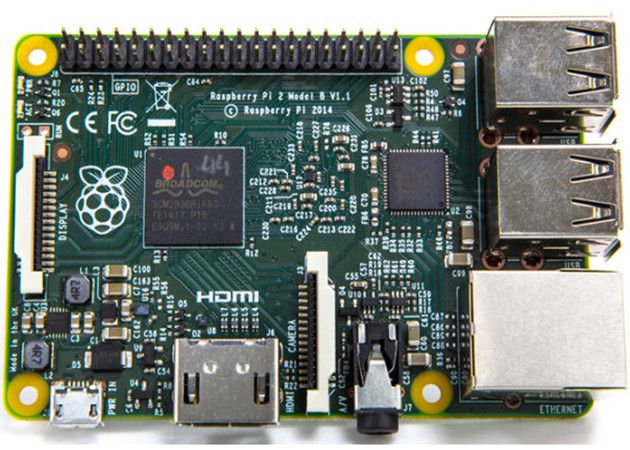
Raspberry Pi 2 es la nueva versión del mini-ordenador con base ARM que lidera en ventas la categoría de “placa única” con más de cuatro millones de unidades desde el lanzamiento de la versión original.
Si te has animado a comprar una al ver el aumento de potencia de la nueva versión con el micro de cuatro núcleos a 900 MHz o el Gbyte de RAM, el soporte a Windows 10bajo el programa Windows Developer Program for IoT o el mantenimiento del espectacular precio de 35 dólares, aquí van cinco cosas que nos proponen desde betanews para realizar cuando recibamos nuestra Raspberry Pi 2.
Compra un chasis
No es obligatorio pero es una buena forma de proteger la inversión teniendo en cuenta el expuesto formato placa de la Raspberry Pi 2. También aumentar su atractivo visualcon una cajita mona (por ejemplo si vas a colocarla en el salón como Media Center) que además suelen incluir los correspondientes disipadores como el modelo propuesto quepuedes encontrar en Amazon que incluso nos permitirá un cierto grado de overclocking.
Su precio de 8 dólares no debe ser un problema como tampoco su instalación que puedes ver en el vídeo siguiente:
Consigue el hardware adicional
Concebida originalmente para tareas de desarrollo, las posibilidades de Raspberry Pi 2 van mucho más allá (como tablet, como traductor universal, como máquina arcade, comorouter anónimo para TOR…) incluyendo donde nosotros le vemos más utilidad para un usuario de a pie, como Media Center.
Dependiendo del uso necesitarás varios productos adicionales. Uno obligatorio seguramente lo tendrás por casa y es una tarjeta microSD. También una fuente de alimentación micro USB (podría valer un cargador de móvil aunque asegúrate que te ofrezca la suficiente potencia) y periféricos como ratón y teclado. Opcional, lo que quieras, adaptador Wi-Fi, un pendrive o disco duro externo, un mando de control remoto para media center, cableado y un largo etc, dependiendo del uso que le vayas a dar. Se venden kits con lo básico a precio económico y seguramente tendrás por casa otros que podrás utilizar.
Instala el sistema operativo en la microSD
Puedes escoger entre alguno de los disponibles oficiales u oficiosos, o algunos porquepuedes instalar varios. Hasta que el proyecto Windows 10 madure la opción pasa por Linux. El más sencillo para empezar es Noobs. Otros son derivados de distros conocidas como Snappy de Ubuntu o Pidora de Fedora, mientras que Raspbmc y OpenElec son los especializados para usos del Media centre XBMC.
Ajusta la configuración en el primer arranque
Con el primer arranque te encontrarás una pantalla de configuración. Lo básico es la buena práctica de escribir una contraseña de acceso o ampliar el sistema de archivospara poder acceder a la totalidad del espacio de la tarjeta micro SD. No es obligatorio y muchos usuarios apuestan por una tarjeta de baja capacidad para el sistema de arranque trabajando con un pendrive o disco externo adicional. A tu gusto.
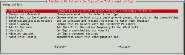
Otra de las funciones es la de overclocking. Sí, sí, también podemos subir de vueltas el procesador. No te pases que no hace tanta falta. Si has colocado una caja y sus disipadores, subiendo 100 MHz (hasta 1 GHz) funciona estable sin problema.
Actualiza firmware y paquetes
Lo primero y principal. Vamos a la línea de comandos y actualizamos:
- sudo apt-get update
- sudo apt-get upgrade
- sudo rpi-update
- sudo reboot
Instalamos paquetes adicionales si es nuestro gusto y siempre teniendo en cuenta el enfoque que vamos a dar a la Raspberry Pi 2. Por ejemplo el reproductor VLC, navegador Chrome o la suite ofimática LibreOffice. Volvemos al terminal:
- sudo apt-get install vlc
- sudo apt-get install chromium
- sudo apt-get install libreoffice
Raspbian utiliza LXDE como entorno de escritorio por defecto. Si quieres utilizar otrotan funcional y ligero como Xfce, nada más sencillo que escribir en el terminal “sudo apt-get install xfce4″.
Las posibilidades son variadas como vemos y si le dedicas tiempo y paciencia la Raspberry Pi 2 es una de esas raras joyas disponibles por 35 dólares.
Fuente:
Subscribe to:
Comments (Atom)


